METAL-CONCRETE
HEAVY DUTY
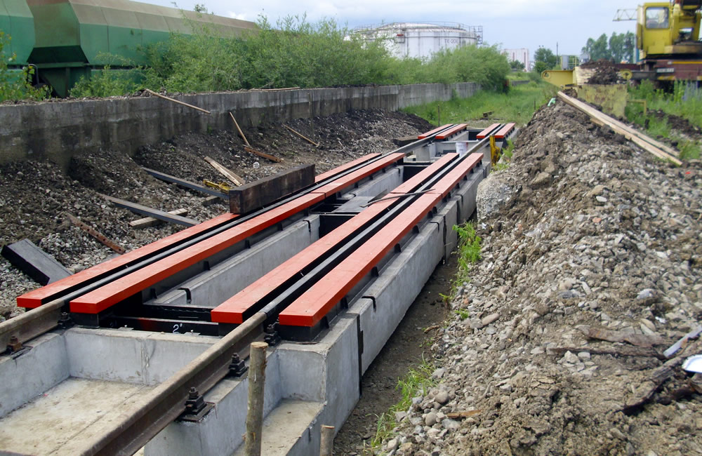
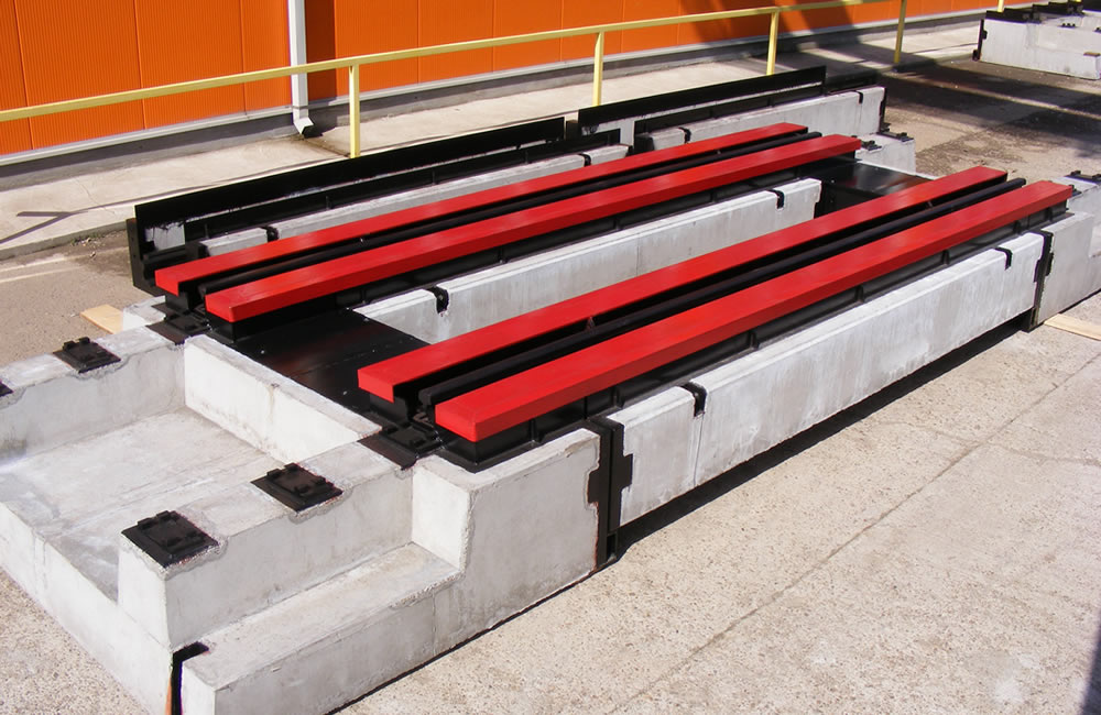
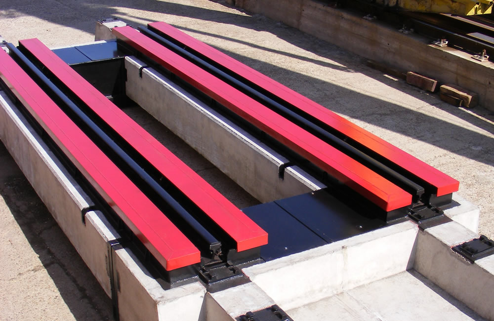
Railway scales in mixed metal-concrete structure with above-ground mounting, directly on the railway infrastructure (without concrete pouring works in situ) relocable, PREMIUM HEAVY-DUTY. Static weighing.
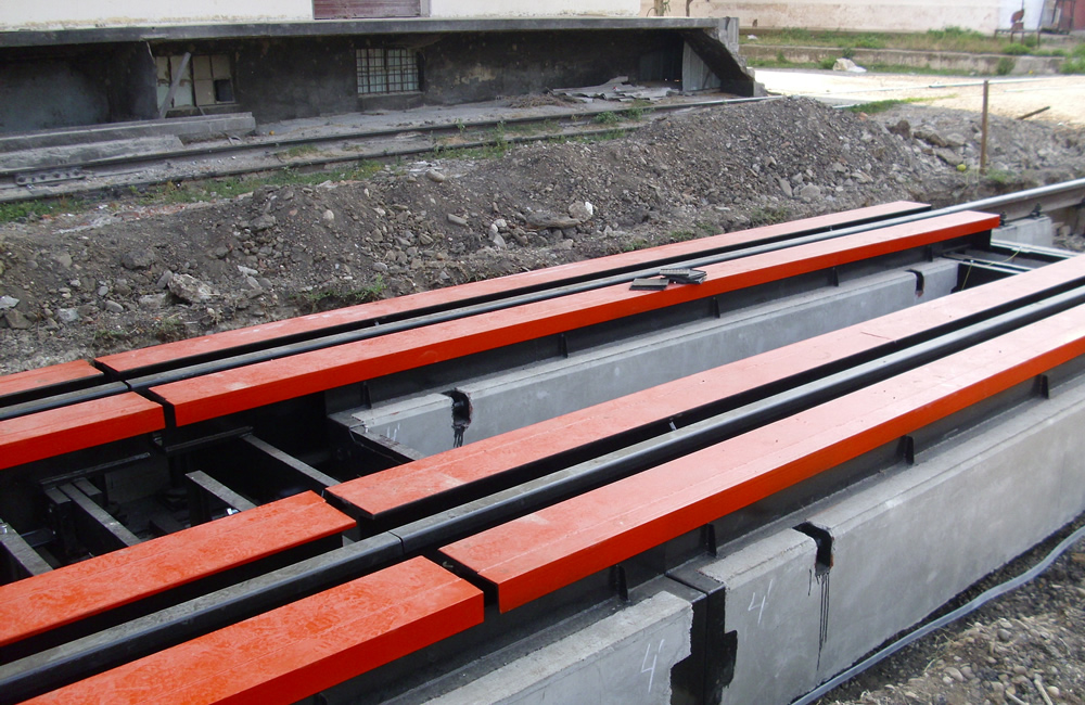
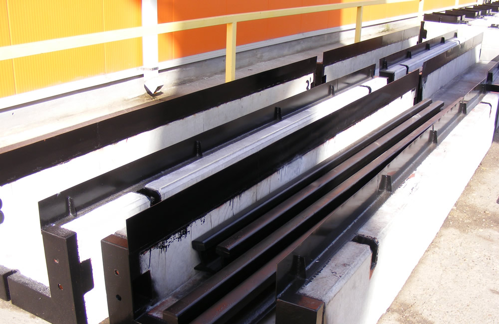
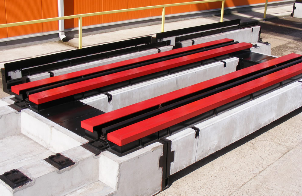
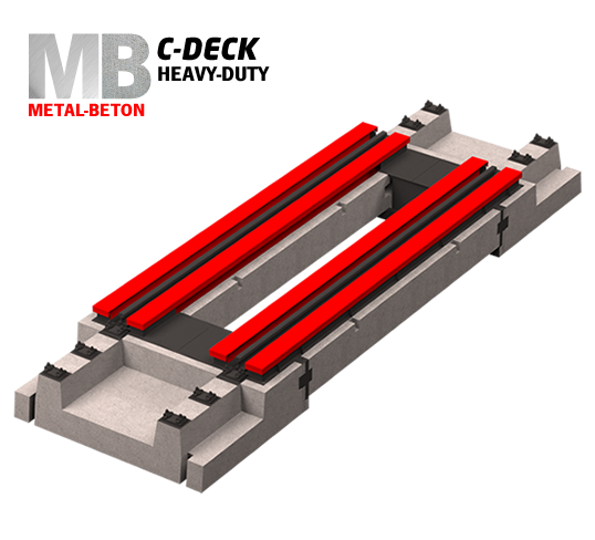
The structure of the C-DECK weighing platform is mixed metal-concrete with metal beams – the active weighing component – mounted on a prefabricated concrete foundation type C45 / 55 according to DIN 1045 which is installed directly on the broken stone infrastructure of the railway.
No in-situ concrete pouring works.
2 or 3 modules
8 or 12 loadcells
- Remarkable qualities of a robust metal-concrete construction, robust and supple
- "Top" model
| LENGTH | 15m | 20m |
|---|---|---|
| PLATFORM | METAL-CONCRETE | |
| CAPACITY (60t/module) [t] | 120 | 120 |
| CLC [k] | 80 | 80 |
| ARROW F [mm] | 1:950 | 1:950 |
| CONSUMPTION | 15m | 20m |
|---|---|---|
| METAL [t] | 10,4 | 15,6 |
| PREFABRICATED CONCRETE [mc] | 8,0 | 13,5 |
MAJOR ADVANTAGES OF THIS DESIGN:
- Modular construction (two or more modules)
- No expensive foundations cast on site
- Installed directly on the broken stone embankment (arranged for this purpose), the works are similar to the replacement of one section of railway with another
- Any high dynamic load, resulting from the movement on the railways, at any speed, has no effect on the scale, as it can be transited by locomotives or train sets.
- Eliminate rainwater drainage problems
- Minimum interruption of the C.F. for assembly: 2 days
- All components are accessible from above
- Simple relocation with full system recovery
- Minimum preventive maintenance
- Recommended for Ex environments, minimum accumulations of explosive gases
- Labyrinth system prevents dust or other deposits (mud, snow, stones)
SIZE SINGING RAIL
The railway scale can have any length in the range 12..60m, length achieved by combining the active weighing modules of 5, 6 or 7m and positioning them at a variable distance in the range 0 / 3..6m (idle area indicated in square brackets) .
Sizing is done by optimizing the placement of the active weighing modules alternating with the inactive (free) areas between them in order to obtain a configuration that allows weighing a train with a minimum (optimal, zero) of untied wagons (optimally, without untying any wagon).
The calculation requires that the bogie axis be positioned as close as possible to the center of the module. According to Instruction 314 of the rules and tolerances for the construction and maintenance of the railway (page 84), no rail coupons below 3m in length are allowed. Therefore, 3m is the minimum length of a C.F. For the sizing process, it is absolutely necessary a list (as complete as possible) with the type of wagons that will transit the railway scale.
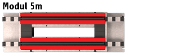
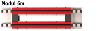
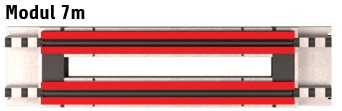
MODULAR DESIGN
GABARITIC TRANSPORT
PLATFORM WEIGHT (1 module):
PLATFORM WEIGHT (1 module):
- 5m: 3,44t
- 6m: 4,48t
- 7m: 6,61t
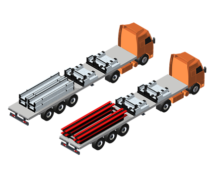
FOUNDATION WEIGHT
- end module (2 buc): 5,1t/pcs
- middle module (2 pcs):
- 5m: 2,28t/pcs
- 6m: 2,81t/pcs
- 7m: 3,26t/pcs
QUICK ON-SITE INSTALLATION
FOUNDATION WEIGHT:
FOUNDATION WEIGHT:
- 5m: 2,28t/buc
- 6m: 2,81t/buc
- 7m: 3,26t/buc
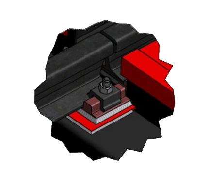
PRINCIPLE FIXING RAILWAY RAIL
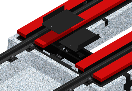
ACCESS OVER THE PLATFORM AND CLEANING CAPABLES
PROTECTION
PROTECTION AGAINST DEPOSITS
The weighing system is not affected in any way by deposits of dust, mud, snow or frost. Any access to the space of the weighing beams is protected by the realization of closing baffles, which do not allow the penetration of mud, snow or stones from the broken stone embankment or other small objects.
The weighing system is not affected in any way by deposits of dust, mud, snow or frost. Any access to the space of the weighing beams is protected by the realization of closing baffles, which do not allow the penetration of mud, snow or stones from the broken stone embankment or other small objects.
LIMITATION SYSTEM
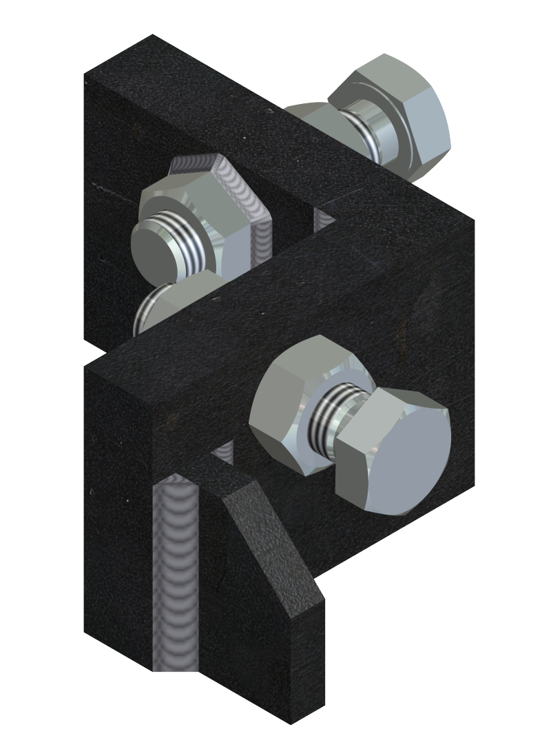
Two pivots at the ends of each beam, to take over the transverse and longitudinal forces
Two pivots at the ends of each beam, to take over the transverse and longitudinal forces
ANTI-CORROSION PROTECTION
Sanding and painting with 2 coats of primer and 2 coats of ACRYLIN 3
Sanding and painting with 2 coats of primer and 2 coats of ACRYLIN 3
- Grit sandblasting with GRACO installation in specially designed cabin
- Painting with airless installation, the final layer thickness is reached at least 120 microns
- 2 coats with a final thickness of at least 60 microns, anticorrosive based on epoxy and polyaminoamide resin, organic additives and solvents.
- 2 coats of ACRILIN E paint, with a final thickness of at least 60 microns
CABLES
Protection against accidental knocks, crushing, rodents, numerous freeze-thaw cycles.
CELLS AND CONNECTION BOX
Protection against vandalism and unauthorized access.
RAILWAY SCALE INSTALLATION
CHOOSE INSTALLATION PLACE
Conditions for the railway:
- Alignment length: minimum 60m.
- Maximum gradual slope on the length of two wagons: +/- 10mm; along the entire length of 60m it can reach +/- 15mm (upstream and downstream of the scale).
- There are no special conditions that must be imposed on the embankment or superstructure in the area in the vicinity of the scale.
- The infrastructure of the scale is the same as the infrastructure of the normal railway.
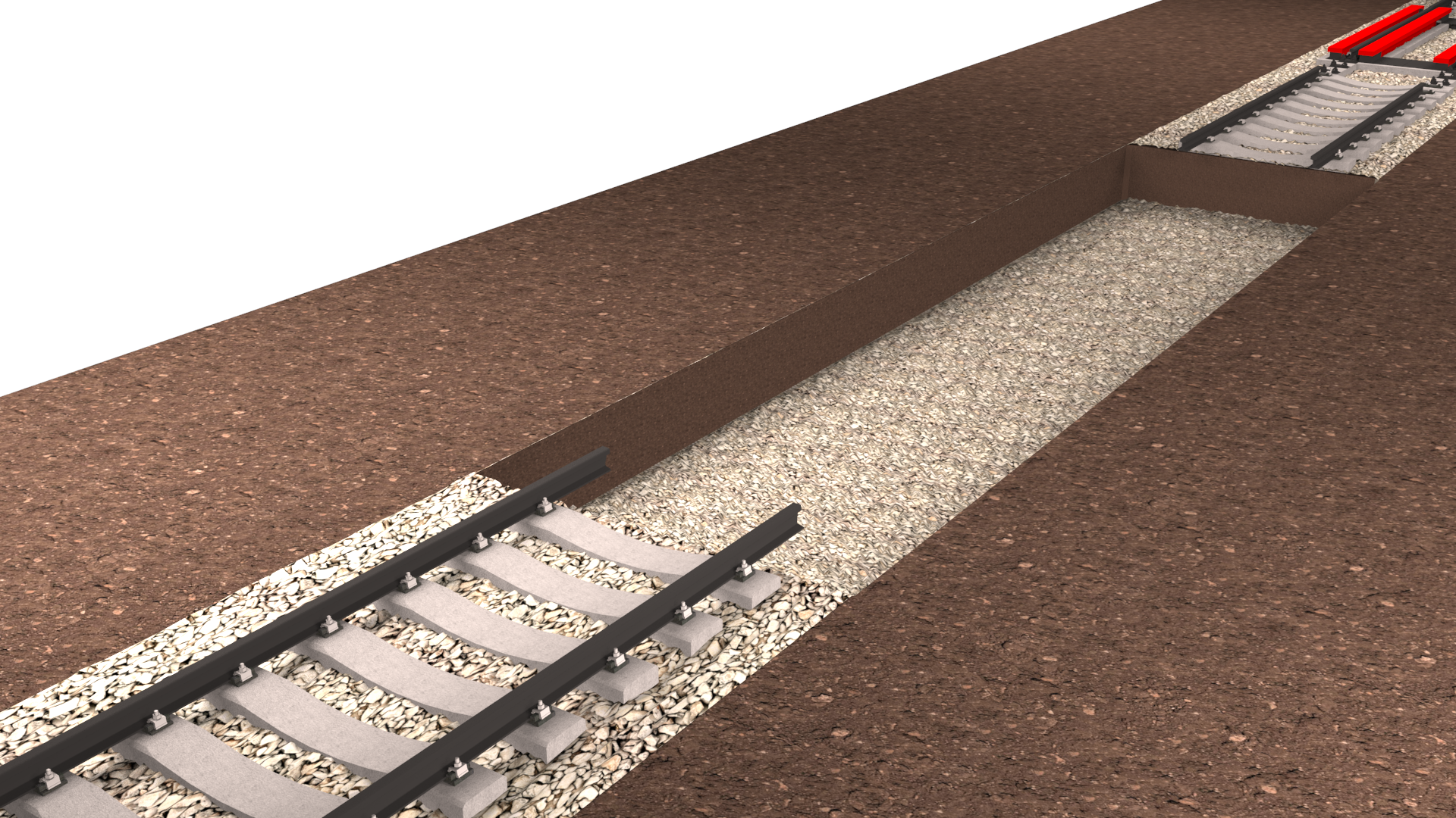
INSTALLATION FILM – RAILWAY WORKS
A. Notices prior to the work:
The design of the works for the installation of a railway scale is carried out by an AFER authorized unit. The documentation verified according to Law 10/1995 ** is submitted to AFER Bucharest (only the standard specifications), for verification and analysis, then to the Lines Division for the authorization of C.F.R. execution.
Obtaining the building permit is the responsibility of the customer.
B. Execution of work:
In summary, the installation process on the 1435mm gauge industrial railway (CN = normal track) consists of:
- Disassembly of rails and sleepers C.F. on a length determined by the size of the railway scale
- leveling and landscaping (removal of the stone layer, where appropriate, to a clean layer (without being impregnated with soil, oils, fuel oil, etc.)
- weighing the factory (FLINTAB Engineers and Constructors, Tecuci, Galati County) - two trucks required
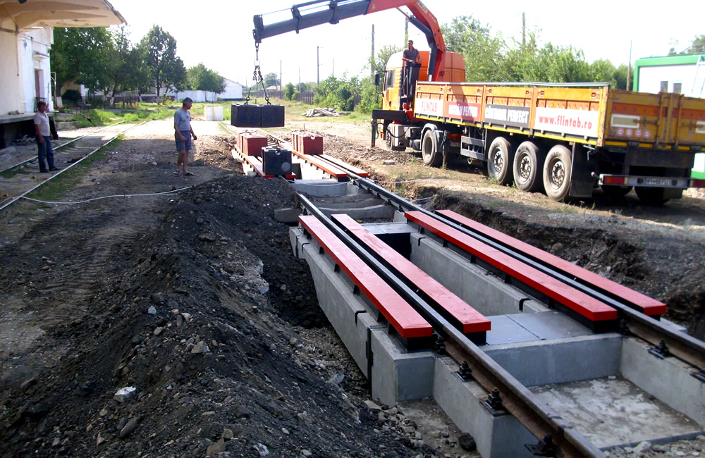
- 25T crane for unloading and mounting
- installation of prefabricated concrete foundations directly on the infrastructure of the broken stone embankment of the railway at 60 cm below the lower level of the rail (NIS)
- assembly of active weighing beams
- restoration of the continuity of the railway and of the broken stone embankment.
The works of C.F. include:
- topographic measurements
- removal of ballast materials from the line to the base of the sleepers / under the sole of the sleepers
- ballast filling between the lines
- ballast compactor with vibratory plate compactor (minimum 95%)
- ancillary operations on line superstructure works: cutting and drilling rails upstream and downstream of the scales
- rectification of expansion joints
- drilling of concrete sleepers on new bed / repairing railways on wooden sleepers
- replacement of rail tracks type 40 where appropriate with normal rail tracks type 49 and small track material
If the existing rail differs from type 49 (old, type 40), the junction of the two types involves an additional cost that will be assessed on a case-by-case basis. The transition from rail type 49 to rail type 40 can only be done with transition coupons (connection eclipses) as follows: along the entire active length of the railway scale, there is a mounted C.F. rail. type 49 with all fastening accessories.
The scale of the scale is extended by an equivalent length of three sleepers, on which are the fastening accessories for the integration of the scale in the current line (for C.F. rail type 49). For connection to rail type 40, rail type 49 on the scale is continued with a 3m section of rail type 49 to which a section of rail type 40 from the existing rail is welded.
The installation instructions are explained in detail in the file "C-DECK railway scale installation instructions"
STEP 1: The old rails are removed along the length of the scale and for another 6m on both sides of it.
STEP 2: Remove the ballast to a depth of at least 600 mm from the upper surface of the cross member.
STEP 3: The installation site is being arranged for efficient drainage.
STEP 4: The ballast bed is being prepared and compacted, which will serve as a foundation for the new scale.
STEP 2: Remove the ballast to a depth of at least 600 mm from the upper surface of the cross member.
STEP 3: The installation site is being arranged for efficient drainage.
STEP 4: The ballast bed is being prepared and compacted, which will serve as a foundation for the new scale.
STEP 5: The sections of the railway scale are transported and unloaded at the installation site.
STEP 6: Weighing and positioning of the weighing platform modules is performed.
STEP 7: The level of the sections of the scale is determined with the help of special tools.
STEP 8: Install the connecting rails.
STEP 6: Weighing and positioning of the weighing platform modules is performed.
STEP 7: The level of the sections of the scale is determined with the help of special tools.
STEP 8: Install the connecting rails.
Transport of the rail scale
Capacity: 120t
Division: 50kg
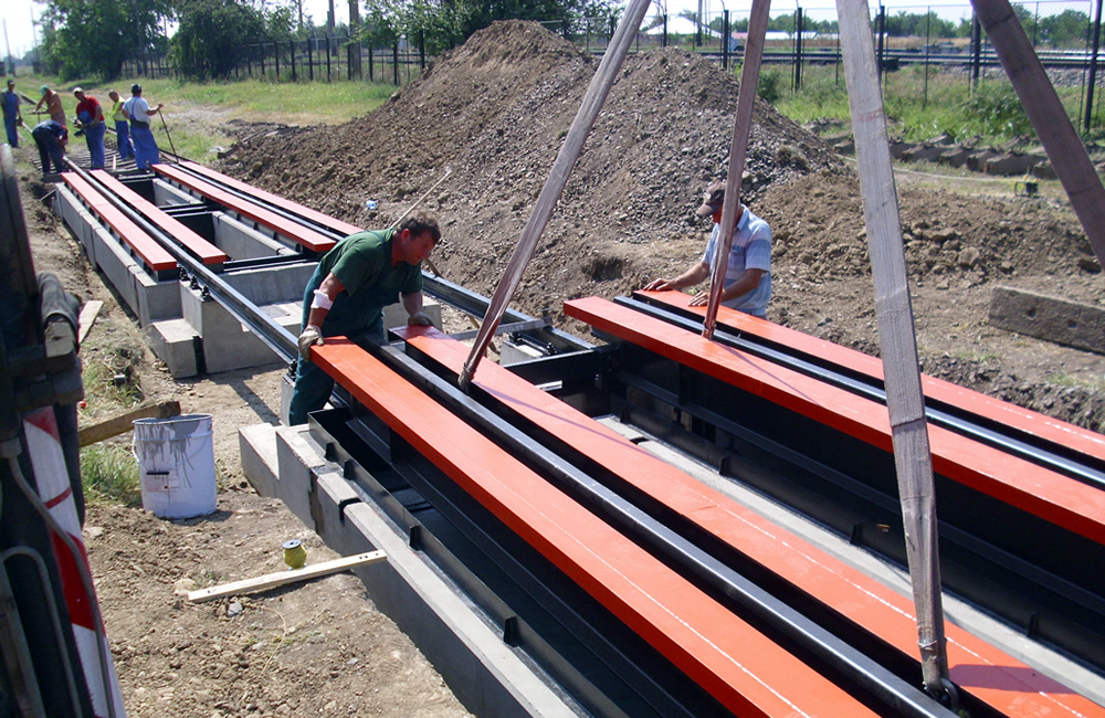
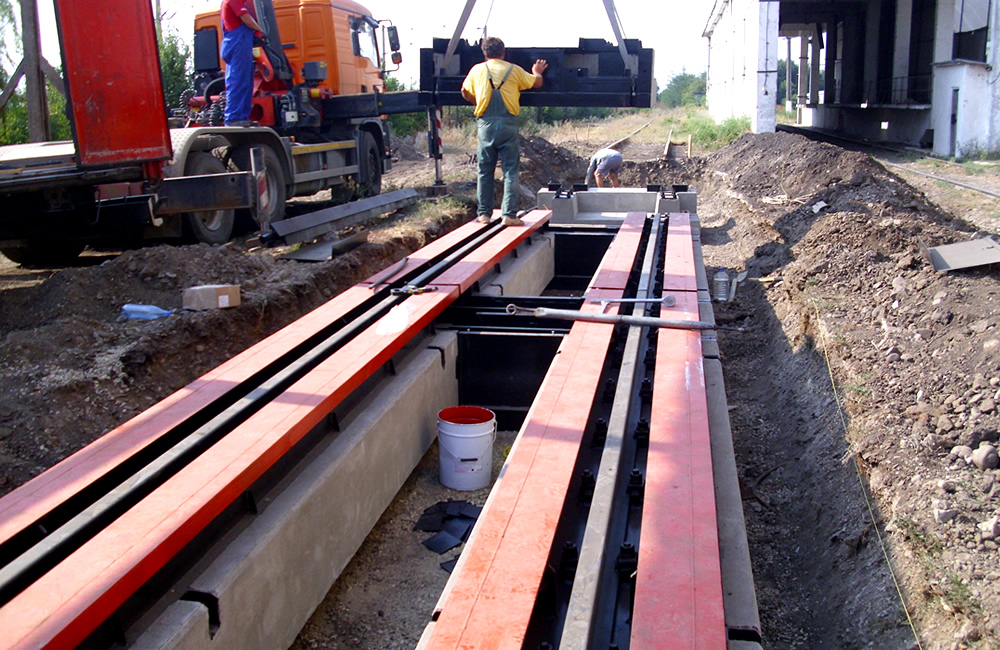
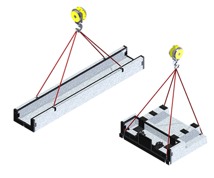
Transportation is oversized, requiring one truck for each module delivered. The installation is quickly carried out on-site with the help of a 25t crane with which the prefabricated concrete and weighing beams will be lifted and will be placed on the specially arranged broken stone embankment.
The minimum alignment length of the railway where the weighing system is to be installed must be 60 m with a maximum gradual slope over the length of two wagons (+/- 10 mm). The scale will fit perfectly into the structure of the railway with the same infrastructure.
Prefabricated end elements as well as U-type prefabricated elements are reinforced with PC52 concrete steel and C45 / 55 brand concrete.
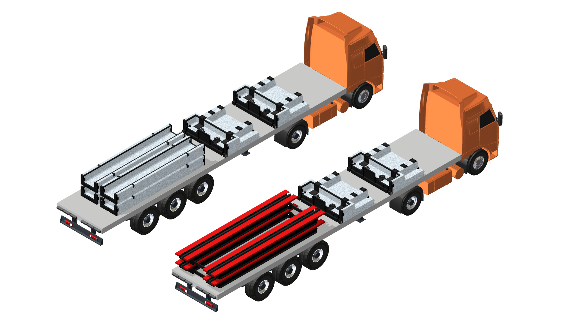
| GABARITIC TRANSPORT | CRANE [t] | WEIGHT MODULE [t] |
|---|---|---|
| 2 trucks | 25t | 3,44t |

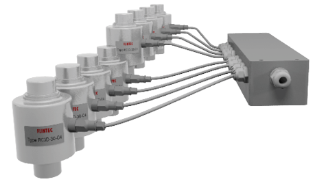
Loadcells FLINTEC GERMANY RC3-30t-C4
- Certification: test certificate no. D09-99.09 issued by PTB GERMANY, a notified body in the European Union
- Material: 17-4 PH stainless steel (1.4548)
- Sealing: completely airtight - by sealing glass on metal; use in "outdoor" industrial environments
- Degree of protection: IP68 / IP69K
- Weighing: allows weighing operations to be performed
- They have the property of always bringing the weighing platform (ROCKER COLUMN loadcell) in a vertical position. The capacity of each cell is 30 tons, according to the best selection practice for maximum reliability over a long service life.
- Safety overload: 200%
- Lateral stress overload: 100%
- Digital filter: automatic with conversion rate adjustment with sample number adjustment (1, 2, 4, 8, 16, 32)
- Asynchronous interface: RS485 half duplex, multidrop with network address, transfer rate adjustable in the range 2400..38400, data bits and parity, programmable parameters

Self-alignment compression cells are the best way to handle large static and dynamic loads!
Summary box
- FRP (fiberglass reinforced polyester) IP66, IP68 glands, silica gel, connection board equipped as standard with electric shock shields.
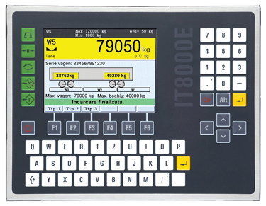
Digital weighing indicator SysTec GERMANY IT8000E
- Certification: EC type-examination certificate D11-09-021 rev.1 issued by PTB GERMANY, notified body in the European Union
- Housing material: stainless steel
- Standard mandatory requirements:
- Standard mandatory requirements:
- RS232 serial communication interface approved for connection to a PC station
- standard equipment with DSD (Data Storage Device) control memory "aliby"; uniquely identified records for weighing traceability assessment
- Technology: MCP (Multi Cell Processing Technology)
- Calibration: digital, through dedicated menu
- Keyboard: On/Off, Sum, Zero, Tare, Print, Function
PC station and printer
Medium market configuration, with pre-installed operating system:
- Processor 2.0GHz
- Memory 2.0GB
- HDD 20GB
- Monitor with native resolution 1280x1024 or 1440x900
- RS232 / USB serial interface or a TCP / IP ethernet interface
- Operating system Microsoft Windows XP SP3, Microsoft Windows Vista SP1 or Microsoft Windows 7
- HP LaserJet PRO P1102 Black and White Laser Printer

Software
Commercial transaction management software system:
- Easy operation based on windows, menus and lists
- Real-time weight monitoring
- Printing, including viewing of issued weighing notes
- Management of weighing data with the issuance of weighing notes and their saving in databases (date, time, COUNTRY, GROSS, NET, product, etc.)
- Reporting commercial transactions for selectable periods of time
- Protection against intent to fraudulently use weighing data
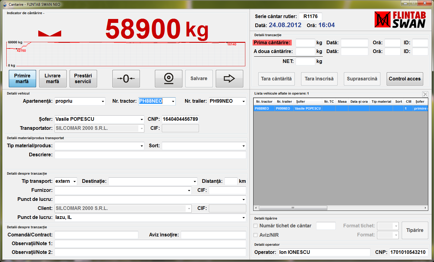
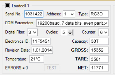
FLINTAB RC3D Software
Specialized software for checking and programming FLINTEC RC3D digital weighing cells, which allows up to 12 simultaneous connections with the mass sensors of the railway scale. The advantages of using these state-of-the-art digital cells are:
- Reliability and precision in weighing
- Easy calibration
- Rapid determination of defective cell in case of repair
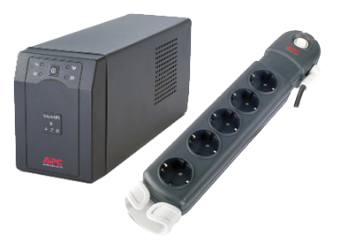
EEP additional electrical protection package
- Flashing socket and quick fuses for protection against surges and electric shocks in the power supply network
- Uninterruptible power supply UPS minimum 500VA
- Extender with the necessary sockets for the system as a whole
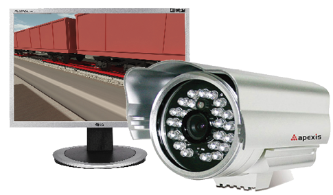
VIDEO EQUIPMENT
Video surveillance system in the cab for viewing the positioning of wagons / choice of weighing configuration with dedicated video monitor.
VIDEO EQUIPMENT
- FLINTEC analog weighing cell set
- Germany RC3 zones 1, 2 (gas) and 21, 22 (dust) in accordance with EEx and IIC T6 ... T4 T130 ° C ATEX
- Set of safety barriers
- Digital weighing indicator for normal area
- Local outdoor display.
IMPORTANT NOTE
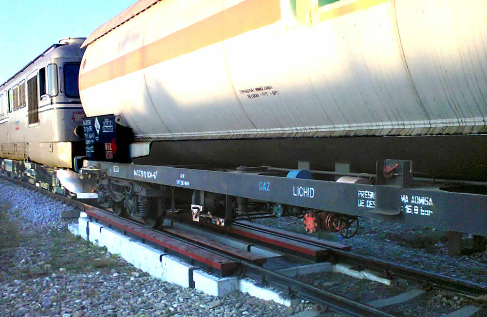
The weight of a wagon is the sum of the weights of each bogie weighed on a section. The weighing program constantly compares during loading the weights of the two bogies which must not differ by more than 300-400kg.
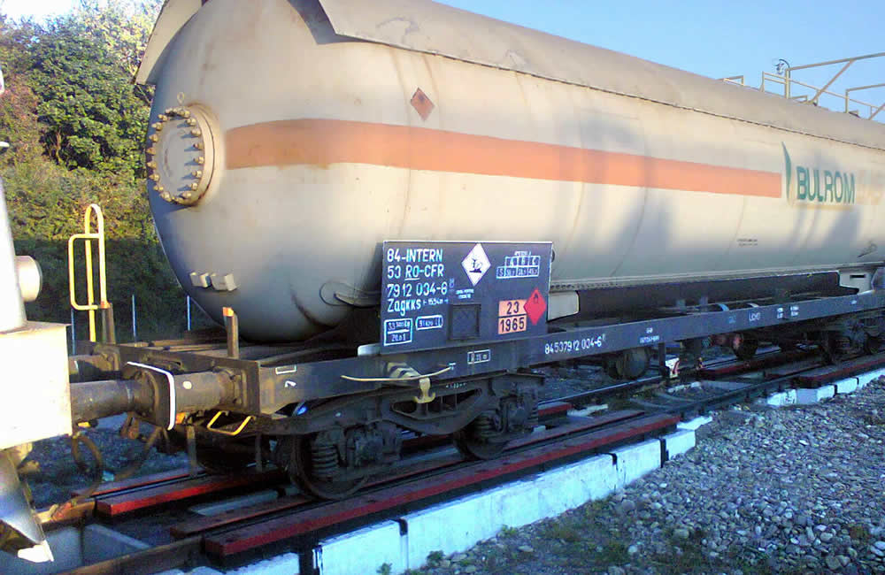
If this value is exceeded, the loading of the liquefied gas tank wagon is automatically blocked. In this way, the weighing system is redundant by constantly checking the weights of the bogies of the loading wagon.
The weighing terminal is also provided with the setting of two values for the pre-alarm of reaching the load weight and the load lock above the value of the weight allowed on the wagon. Loading is done by controlling the fine-coarse flow at the beginning of loading and coarse-fine at the end of loading.
CSI VERSION
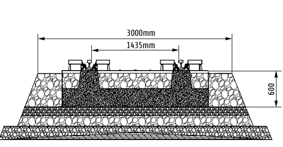
Normal gauge railways, 1435mm, characteristic of most European, Asian and African countries.
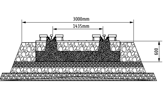
Railways for Ukrainian or Russian wagons, industrial railway line CL = wide track, gauge 1520mm.
C-DECK railway scales are delivered on request with a 1520mm wide gauge for CIS states. They can also be delivered in special construction with double gauge:
- European gauge 1435mm
- Wide gauge 1520mm
The advantage of the special double gauge construction is that the wagons can be weighed regardless of their gauge.